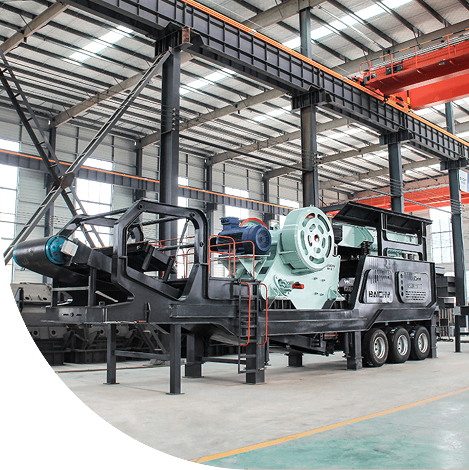
Products Display

Material Application

Jigging machine Features

The basic composition of jigger is jigging chambers, also called jigging boxes, and there are screens in each chamber.Water and raw ore will be fed from one end of the jigger screen, the ore granules will move in the vertical alternative water-flows. Layers will be formed because of density difference of materials. The minerals with small density will be in the up layer and will flow together with the up pulp flow while material with bigger density will be in the down layer and will discharged from the down discharging port as jigging concentrate.

specification

*The output will vary according to different materials, feed particle size and other factors

Type Model Jig room containing the surfac shape Jig room Stroke data Divide Max. feeding size (mm) capacity (t/h) water consumption (t/h) Power (kw)
Chang* Wide (mm) Single room (m²) Rows Room number With a total area of (m²) Stroke (mm) Chong times (times /mm)
Lateral drive LTP-34/2 Rectangle 450*300 0.135 Single 2 0.27 0.58 2-5 320-420 12 2-10 4-10 1.1
Bottom drive LTA-1010/2 Rectangle 1000*1000 1 Single 2 2 0.5 0-25 250-350 5 5-15 10-20 2.2
Side drive LTC-69/2 Rectangle 900*600 0.54 Single 2 1.08 0.56 0-50 220-350 12 6-9 40-60 1.5
Side drive 2LTC-366/8T Trapezoid 600*(300-600) 0.2-0.34 Double 8 2.16 0.68-0.41 0-50 120-300 5 3-6 20-40 1.1*2
Side drive 2LTC-6109/8T Trapezoid 900*(600-1000) 0.58-0.86 Double 8 5.76 0.52-0.35 0-50 120-300 5 10-20 80-120 2.2*2

Product Recommendation

Profession Achieves High Quality | Built Tough | Works Smarter

logo.png
mobile-crusher-kefu.png